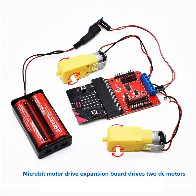
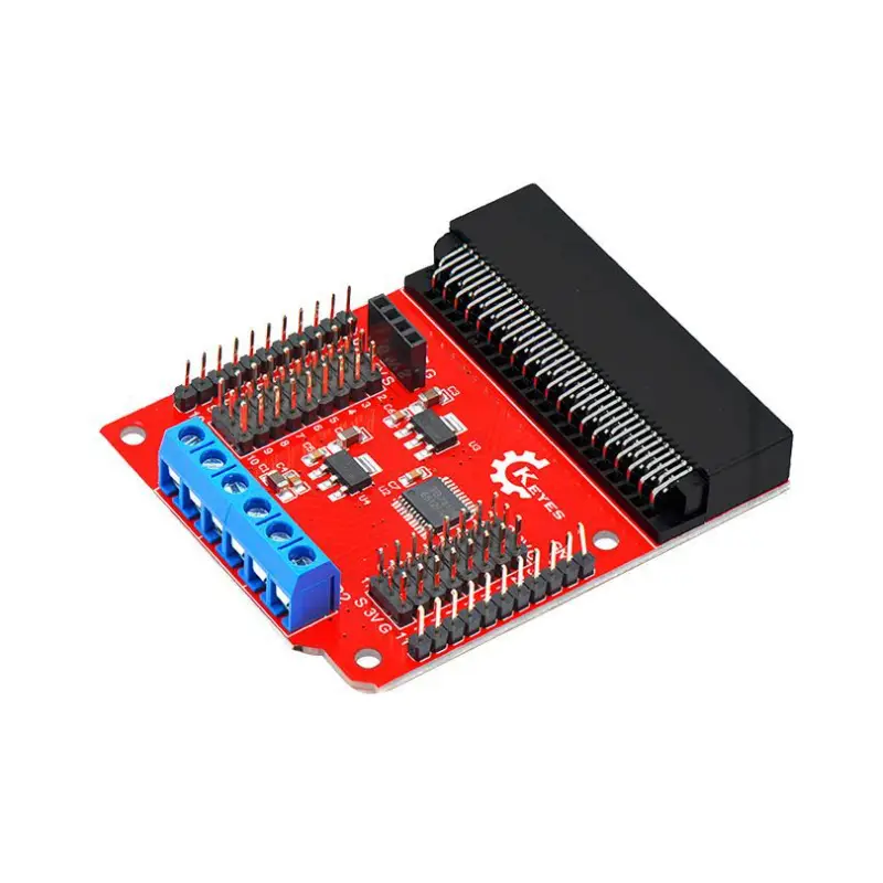
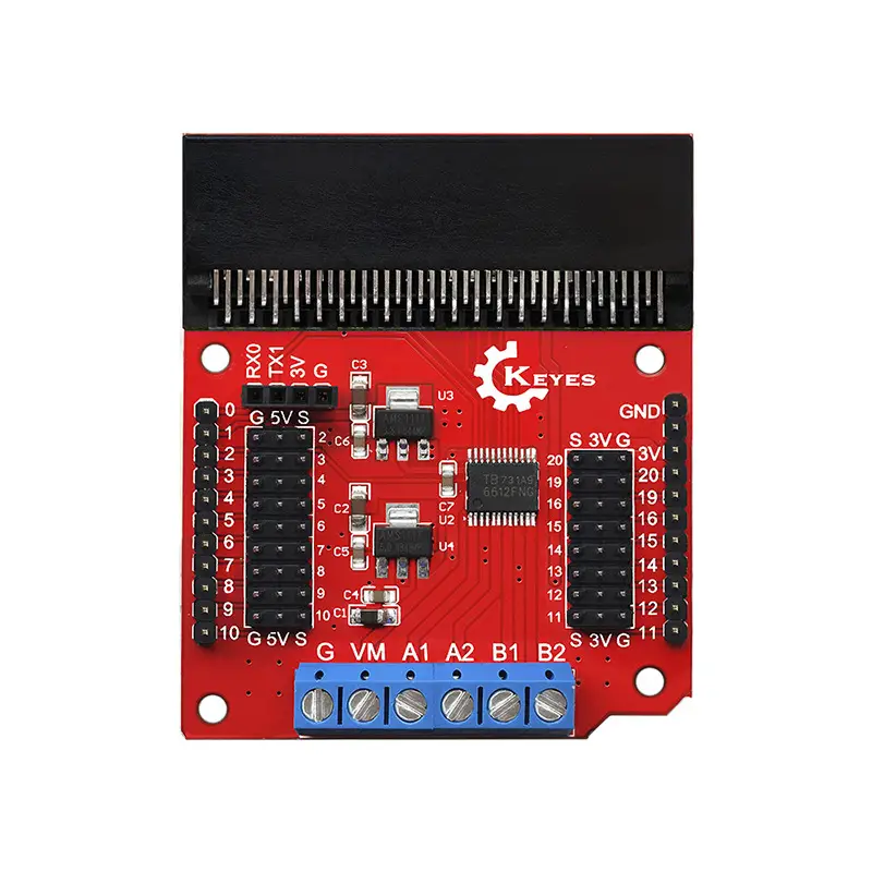
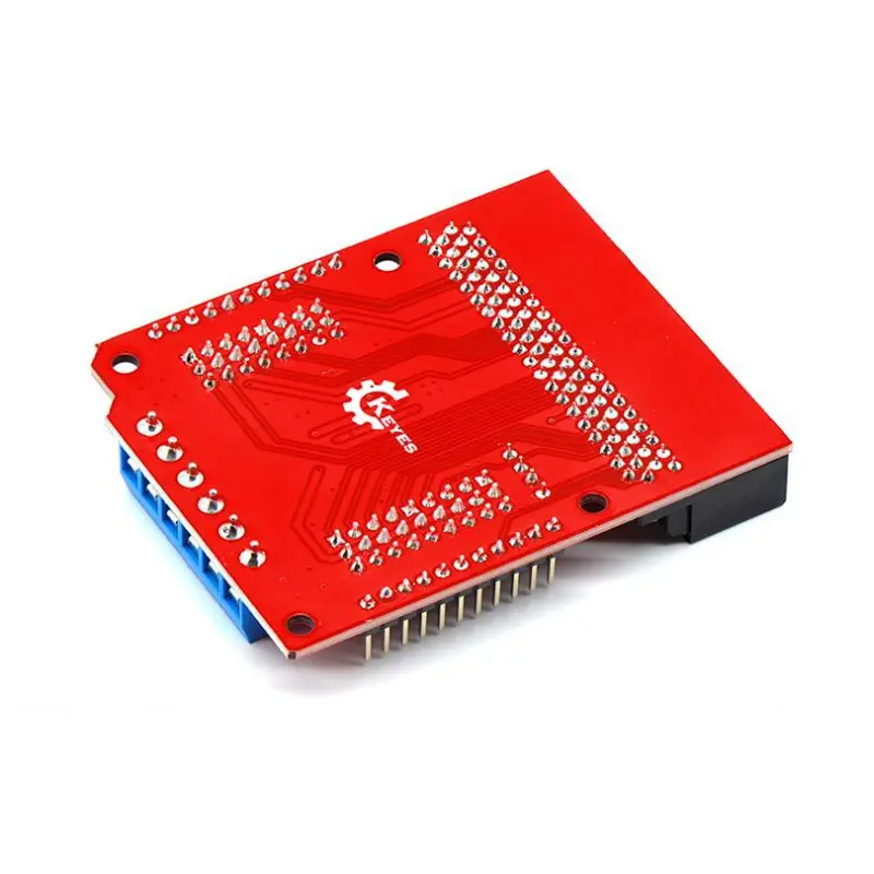
Keyes micro:bit Motor Driver Expansion Board (KE0136) 1. Introduction The Keyes micro:bit Motor Driver Expansion Board (KE0136) is designed specifically for the BBC micro:bit. Equipped with the TB6612FNG driver chip, it can drive two DC motors or one stepper motor, making it ideal for maker projects requiring motion control such as smart cars, robotic arms, etc. This expansion board features regulated 3.3V/5V output and 3PIN interfaces, facilitating the connection of sensors and communication modules. It adopts red eco-friendly PCB technology, ensuring excellent quality and an attractive appearance. The micro:bit is an entry-level development board launched by the British Broadcasting Corporation (BBC) for youth programming education. It is compatible with Microsoft’s PXT graphical programming environment (MakeCode), enabling beginners to get started quickly across multiple platforms (Windows, macOS, iOS, Android, etc.) without downloading a compiler. 2. Features Multi-channel Motor Output 2 channels of DC motor output, supporting forward rotation, reverse rotation, braking, stop and other modes. PWM frequency up to 100 kHz max. High-current Driving Capability The TB6612FNG chip delivers a continuous output current of up to 1.2A per channel, with a peak starting current of 2A/3.2A, meeting the requirements of most small vehicles and stepper motors. Rich Interfaces Micro:bit pins are extended via 3PIN (VCC/GND/Signal) interfaces. A UART communication interface is also provided for easy connection of Bluetooth modules or other serial devices. Regulated Power Supply On-board 3.3V and 5V voltage regulator chips supply power to the micro:bit, the expansion board itself, and other peripherals simultaneously. Eco-friendly Manufacturing Process Red eco-friendly PCB is adopted, combining aesthetic appeal with durability and complying with green production standards. 3. Specifications Parameter Specification Input Voltage DC 6–12V (recommended to match the rated voltage of the motor used) Driving Current Continuous operating current per channel ≤ 1.2A Peak Current 2A/3.2A for starting or short-term peak operation Driver Chip TB6612FNG (dual H-bridge driver) Dimensions Approx. 70mm × 58mm Compatible Motherboards BBC micro:bit (V1 / V2) Interface Type 3PIN interface + motor terminals + UART extension + external power terminal Operating Environment -10℃ ~ +50℃ 4. Working Principle Signal Transmission When the micro:bit is plugged into the expansion board, its GPIO, PWM, UART and other signals are transferred to the input terminals of the driver chip via on-board circuits. Motor Control The TB6612FNG generates corresponding driving outputs for DC motors based on control signals (IN1/IN2/PWM) from the microcontroller, enabling forward rotation, reverse rotation, braking and stop functions. Power Distribution An external 6–12V power supply powers the motors, and the voltage stabilizing circuit provides 3.3V/5V output for the micro:bit and other extended functional modules. Extended Applications More sensors, Bluetooth modules or other communication devices can be connected to the micro:bit via the 3PIN interfaces, realizing intelligent control or wireless data transmission. 5. Interface Description micro:bit Slot Insert the micro:bit motherboard (gold finger end) vertically into the expansion board socket, ensuring the micro:bit LED display faces outward. Motor Terminals (M1, M2) Used to connect two DC motors or one stepper motor (wiring must follow the correct phase sequence). External Power Interface A DC jack or terminal (varies by specific version) is used to connect a 6–12V power supply, which powers the motors and on-board circuits. 3PIN Pin Interface Common micro:bit pins such as GPIO, I2C, SPI and UART are extended via 3PIN (VCC/GND/Signal) interfaces for quick wiring. UART Interface Provides a 2-wire RX/TX port, which can be directly connected to Bluetooth modules or other serial modules. Power Selection/Regulating Circuit The board features 3.3V/5V output pins, usually labeled as 3V / 5V / GND. Dupont wires can be used to supply power to sensors or low-power modules. 6.The following briefly illustrates the logical connections between the micro:bit, expansion board, DC motors and input power supply: The micro:bit is connected to the driver chip via the expansion board slot; M1 and M2 are used to connect DC motors; The external power supply with an input of 6–12V drives the motors and supplies power to the micro:bit after voltage stabilization; Optional connection to additional sensors or communication modules is supported, with 3.3V/5V power and UART resources available.